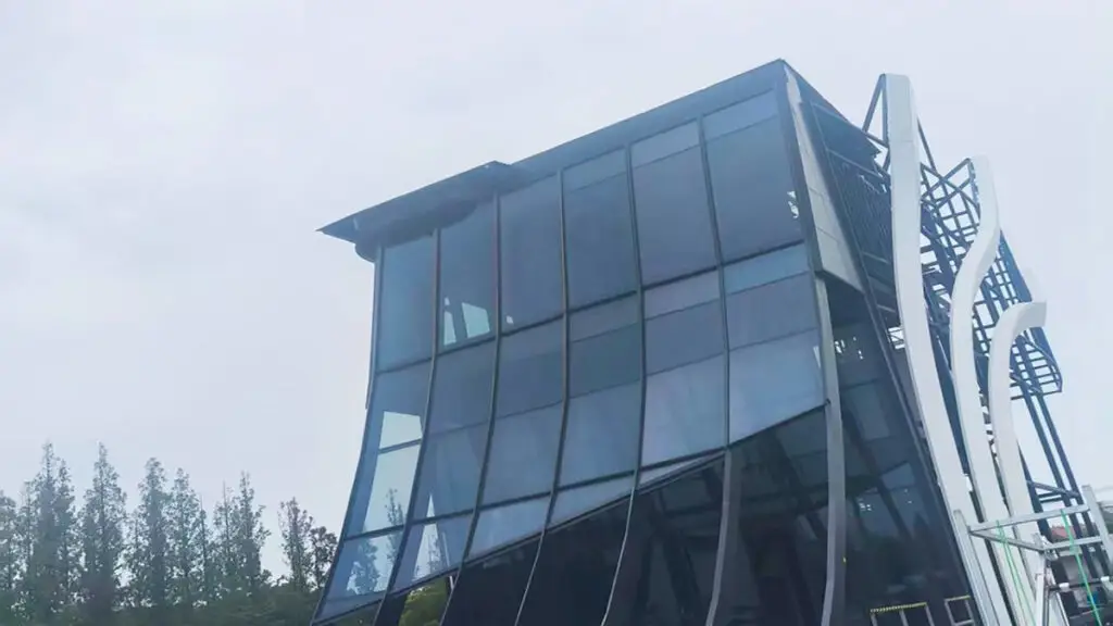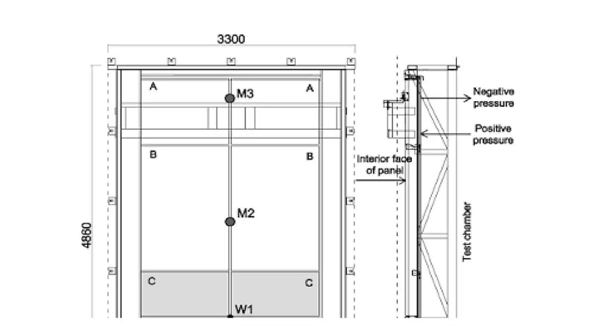
A façade looks perfect on drawings. The question is: how will it perform when exposed to wind, rain, building movement, and temperature extremes? That is the purpose of a Performance Mock-Up (PMU).
PMU testing is much more than a contractual requirement or a final pass/fail exercise. Air infiltration, water penetration, structural wind load, interstory movement, thermal cycling and condensation are not isolated challenges in a real building. They interact.
Based on WHTB’s experience with a complex curtain wall PMU, here is how we approached the process—from engineering and detailing through fabrication, installation and the final testing sequence.

1. PMU Starts with the Drawings
A successful PMU does not begin in the laboratory, it begins at the design table.
For a project we supplied, the curtain wall engineering and PMU development were based on U.S. façade testing standards, including:
- ASTM E330/E330M — Structural performance under uniform static air pressure
- ASTM E283/E283M — Air leakage through exterior windows, curtain walls and doors
- ASTM E331 — Water penetration under uniform static air pressure
- AAMA 501.1 — Dynamic water penetration
- AAMA 501.4 — Interstory horizontal movement
- AAMA 501.7 — Vertical interstory movement
- AAMA 501.5 — Thermal cycling
The real engineering challenge is understanding how the complete curtain wall will behave throughout the entire testing sequence.
Designing for a 15 mm displaced condition: one particularly important requirement was that the upper-level curtain wall panels had to remain 15mm above their normal position during portions of the test program.
We asked several practical questions:
- Could components collide during movement?
- Would gasket engagement remain sufficient?
- Would drainage paths continue to function?
- Would the aluminum profiles and connections still transfer loads correctly with the upper panels displaced by 15mm?
The profile stresses and load-transfer paths were therefore checked under the displaced condition – not just the theoretical normal position.
This is an important principle in PMU engineering: Don’t design only for the position in which the façade is installed. Design for every position the façade will experience during testing—and ultimately during the life of the building.

2. Establishing the PMU Test Protocol
Before testing began, the project specifications were carefully reviewed and the testing requirements, parameters and sequence were coordinated with the façade consultant.
The final key parameters included:
- 2000 Pa Design wind pressure
- 300 Pa Air infiltration/exfiltration pressure
- 720 Pa Static water pressure
- 15mm Upper-panel displacement
- 29 procedures test sequence
The sequence included:
- Covering the PMU with plastic film for chamber leakage evaluation
- Raising the upper slab/panel condition by 15mm
- 25 opening-and-closing cycles
- 50% structural preload
- Static air infiltration/exfiltration
- Static water penetration
- Dynamic water penetration
- 100% structural design wind load
- Inward/outward interstory movement
- Up/down vertical interstory movement
- Left/right interstory movement
- Five opening, closing and locking cycles
- Repeat air infiltration/exfiltration
- Structural wind-load testing
- Opening, closing and locking operation
- Repeat air infiltration/exfiltration
- Repeat static water penetration
- Repeat dynamic water penetration
- Construction of the thermal chamber
- Thermal cycling
- Condensation evaluation
- Removal of the thermal chamber
- Opening, closing and locking operation
- Repeat air infiltration/exfiltration
- Repeat static water penetration
- Repeat dynamic water penetration
- 150% structural overload
- 150% interstory movement testing
- Final opening, closing and locking operation
The repeated tests are particularly important. Passing a water test before structural movement is one thing.
Remaining watertight after the façade has experienced wind load, interstory displacement and thermal cycling is a much stronger demonstration of system robustness.

3. Fabrication: PMU Performance Is Built into the Details
Once engineering was complete, attention shifted from calculations to workmanship.
For this project, the PMU included structurally glazed curtain wall construction, making structural silicone application and joint preparation critical to system performance.
We coordinated directly with the structural silicone manufacturer to confirm the appropriate primer and application sequence.
But the larger lesson was that PMU quality depends on hundreds of details that may appear insignificant individually. Every penetration matters.
During assembly, screws were installed only after sealant application. Bolts located within aluminum cavities were carefully treated, and profile holes and penetrations were sealed to prevent unintended water paths.
We reviewed:
- Panel fabrication drawings
- Frame assembly drawings
- Gasket interfaces
- Drainage routes
- Sealant locations
- Fastener penetrations
- Internal cavities
- Water-management paths
Why this level of attention? Because water does not care where the designer intended it to go. A small hole on the screw, an interrupted sealant bead or an incorrectly terminated gasket can create a pathway that only becomes visible when the system is exposed to pressure.

4. Installation: Protecting the Designed Drainage Strategy
Even a well-engineered and correctly fabricated curtain wall can fail if the installation does not preserve the intended air and water management strategy.
For this reason, installation quality control was treated as part of the PMU itself. Water was filled to the top elevation of the drainage trough and maintained for at least one hour.
Every critical location was inspected for leakage. After draining, drainage openings were checked again to confirm that the designed water paths remained unobstructed.
Particular attention was also given to:
- Waterproofing treatment at four-way panel intersections
- Membrane installation at cross joints
- Sealing of starter conditions
- End sealing of horizontal transoms
- Continuity of internal drainage paths
The objective was not simply to “add more sealant.” It was to ensure that every layer of the curtain wall performed its intended function.
5. The PMU Test Begins
Before testing, the mock-up, instrumentation and sensors were inspected and test equipment was calibrated.
The upper-level panels were then raised 15mm, creating the specified maximum theoretical joint condition. This displaced condition was maintained as required during testing. Now the façade had to prove what the engineering predicted.
Operational cycling – 25 cycles
Before performance testing, every operable window and door was fully opened, closed and locked 25 times.
This verified that hardware, locking points, gaskets and moving components continued to operate correctly before environmental loading began.
50% structural preload
In accordance with the project test procedure based on ASTM E330/E330M, the specimen was subjected to positive and negative pressures of 1,000 Pa – 50% of the 2,000 Pa design wind pressure—for at least 10 seconds.
After unloading, the façade and its connections were inspected for damage or failure.
The PMU was then ready for the environmental performance tests.

6. Air Leakage – Finding What Cannot Be Seen
Air leakage testing was performed at ±300 Pa based on ASTM E283/E283M. The process is more sophisticated than simply pressurizing the chamber and reading a number.
First, the PMU exterior was covered with plastic film so the leakage attributable to the test chamber itself could be established.
After chamber leakage was measured, the plastic film was removed.
Measurements were then taken for the fixed curtain wall areas and operable areas under positive and negative pressure.
By accounting for chamber leakage and the leakage associated with different façade components, the actual air leakage attributable to each portion of the curtain wall could be determined and normalized by area.
This provides something extremely valuable: A measurable indication of the continuity of the façade air barrier.
7. Static Water Penetration – 720 Pa
Static water penetration testing was conducted based on ASTM E331.
The curtain wall exterior was sprayed at approximately 3.4 L/m²·min for 15 minutes while maintaining a 720 Pa positive pressure differential. The acceptance criterion was no uncontrolled water penetration. This distinction is important.
8. Dynamic Water Penetration – Simulating Wind-Driven Rain
Dynamic water penetration testing was performed based on AAMA 501.1.
The façade was exposed to dynamic airflow corresponding to the specified 720 Pa condition, with an average façade wind speed of approximately 34.3 m/s, while water was applied at approximately 3.4 L/m²·min for 15 minutes.
This test introduces a different challenge from static chamber pressure. Water is driven across the façade by high-velocity airflow, challenging joints, gaskets, interfaces and drainage paths under conditions intended to represent severe wind-driven rain.

9. Structural Wind Load – 100% Design Pressure
The curtain wall was then subjected to its full 2,000 Pa design wind pressure under the project procedure based on ASTM E330/E330M.
The sequence included: 50% positive pressure → 100% positive pressure → 50% negative pressure → 100% negative pressure
Each stage was maintained for the specified duration, with system deflections measured and recorded. The evaluation considered the applicable project limits for mullions, cantilevered members, glass and metal panels.
But the engineering question goes beyond a single deflection number: Can the façade accept the load, transfer it through its framing and connections, and return without unacceptable damage or permanent deformation?
10. Interstory Movement – When the Building Moves but the Façade Must Continue Working
Buildings are not static. Under wind, seismic effects, structural deflection and other actions, floors move relative to one another.
The curtain wall must accommodate that movement without losing glass support, damaging profiles, disengaging gaskets or destroying critical seals. Three movement directions were evaluated.
Inward & Outward movement
Based on the project procedure referencing AAMA 501.4, the intermediate structural beam was displaced perpendicular to the primary façade plane.
The movement sequence was: 40mm outward → neutral → 40mm inward → neutral
Three complete cycles were performed.
Vertical movement: Based on the project procedure referencing AAMA 501.7, the intermediate beam was displaced vertically: 5mm downward → neutral → 15mm upward → neutral. Five complete cycles were performed.
Left & Right movement
The intermediate structure was then displaced parallel to the façade: 40mm left → neutral → 40mm right → neutral. Three complete cycles were performed.
Following these tests, bolts, profiles, glass, panels, gaskets and sealant interfaces were inspected. No unacceptable damage, permanent deformation, gasket disengagement or sealant failure was permitted.
And then came the critical question: After all that movement, could the curtain wall still keep air and water outside?
That is why the air leakage, static water and dynamic water tests were repeated.

11. Thermal Cycling – From −18°C to +82°C
Wind and rain are only part of the façade’s environment. Temperature creates another type of movement – one that happens every day throughout the life of a building.
For the thermal cycling program based on the project requirements and AAMA 501.5, the exterior environment ranged from: −18°C to +82°C
While the interior condition was maintained at approximately: 21 ± 3°C
The curtain wall underwent six thermal cycles.
The evaluation considered whether system components could accommodate thermal movement without unacceptable bowing, deformation, cracking, glass damage, structural-seal failure or excessive stress in finishes, materials and fastening systems.
This is where details such as expansion allowances, gasket behavior, sealant joints, anchors and material interfaces become critical.

12. Condensation Evaluation
Following thermal cycling, the system was also evaluated for condensation behavior.
Under the specified test conditions, the system was allowed to reach thermal equilibrium and the condition was maintained for 12 hours.
The specified winter conditions included approximately: Exterior 7.8°C, Interior 21°C, Interior relative humidity 50%
Thermocouples were positioned at potential condensation locations, with surface temperatures evaluated against the calculated dew point.
This helps identify thermal bridges and locations where interior surface temperatures could fall below the dew point under the specified environmental conditions.
13. The Final Challenge – 150% Structural Overload
Passing the design wind load is not the end of the PMU. The system was finally subjected to 150% of the 2,000 Pa design wind pressure.
The loading sequence included: 75% positive → 150% positive → 75% negative → 150% negative
The peak test pressure therefore reached 3,000 Pa in both positive and negative directions.
Permanent deformation was measured after unloading, with the project acceptance criterion limiting permanent deformation to the specified allowable value. This is no longer about normal service conditions. It is about demonstrating reserve structural capacity.
14. 150% Interstory Movement
The final movement test pushed the system beyond the original design movement. Horizontal displacement increased from ±40 mm to: ±60 mm.
The intermediate structure was moved: 60 mm left → neutral → 60 mm right → neutral; followed by: 60 mm outward → neutral → 60 mm inward → neutral
Three complete horizontal cycles were performed in accordance with the project test procedure.
At this stage, the primary requirements included maintaining glass integrity and preventing unacceptable permanent deformation of the framing system.
After everything the façade had experienced – pressure, water, wind, multidirectional movement and thermal cycling – the system still had to maintain its fundamental structural integrity.
What Does a PMU Really Prove?
It proves whether hundreds of components, interfaces and installation details can work together as one façade system. That distinction matters.
A successful PMU is the result of a chain: Engineering → Detailing → Material Selection → Fabrication → Assembly → Installation → Testing → Verification
Break one link, and the laboratory will often expose it. This is also why we believe PMU work should start long before the specimen arrives at the testing facility.
The best PMU problems are not the ones successfully repaired in the laboratory.
They are the ones identified in drawings, calculations, fabrication reviews and factory quality control before the test ever begins.
For façade contractors, consultants, architects and general contractors, that is ultimately what PMU testing provides: certainty before repetition.
Before thousands of square meters of curtain wall are fabricated and installed, build it once, move it, pressurize it, soak it, heat it, cool it—and learn from it.
At WHTB Glass, we see performance mock-ups not simply as tests to pass, but as an opportunity to validate how façade engineering, glass, aluminum systems, sealants, fabrication and installation come together under real performance demands.