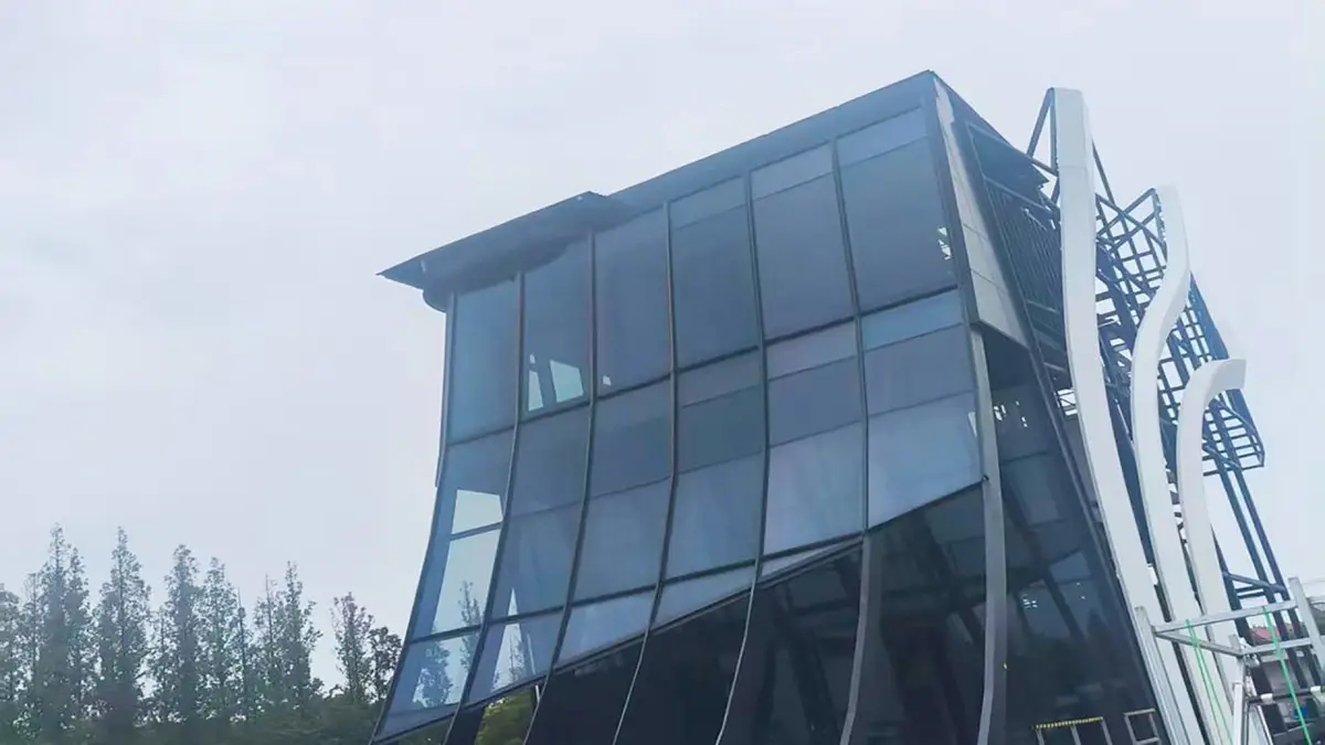
Every major facade project has a moment where the design stops being a drawing and becomes a physical object you can stand in front of, touch, and review. That’s the visual mock-up – VMU.
Done well, it resolves specification ambiguity before fabrication starts, aligns the owner’s visual expectations with what the system can actually deliver. Done poorly – it shifts those problems into the construction phase, where they cost orders of magnitude more to resolve.
WHTB has been involved in VMU processes across multiple project types – from high-rise curtain wall to specialty facade systems. Here is how it works.
Step 1 – Building the VMU Platform
The VMU platform is a full-scale, freestanding structure built to replicate a representative section of the proposed facade system. It is a built assembly – typically one to three bays wide and two to three floors tall – that replicates the actual installation conditions: anchor points, structural connections, drainage paths, and inter-panel joinery.
A project with multiple facade types – glass, aluminum panel, stone cladding, UHPC elements – may require a platform that shows transitions between systems, not just each system in isolation.

Step 2 – VMU Types
A VMU is not a single thing, the multiple material systems require separate mock-up assemblies:
Glass VMU – the most common type. Full-scale IGU panels installed in the curtain wall or window wall framing system, with all sightlines, gaskets, and cover caps in place. The glass VMU is the primary reference for color, reflectivity, and visual clarity under natural light.
Aluminum Panel VMU – panels fabricated and finished to the specified alloy, and surface treatment. The aluminum VMU is the reference for color consistency, surface texture, and the visual behavior of the finish across different panel orientations and lighting conditions.
Stone VMU – natural or engineered stone panels installed in their specified attachment system. Stone has inherent variation in color and veining; the VMU establishes the acceptable range, not a single point.
UHPC VMU – Ultra-High Performance Concrete panels establishes form, surface texture, color, and the visual behavior of the exposed aggregate or formed finish. UHPC panels have long production lead times, making early VMU approval critical to the overall schedule.

Step 3 – VMU Components
Beyond the primary cladding panels, the VMU must demonstrate every integrated facade component in its installed condition:
- Awnings – weather protection elements that require structural verification under wind and snow load, as well as visual integration with the facade plane
- Decorative grids – applied or structural grid elements that define the visual rhythm of the facade; alignment, shadow line depth, and color contrast all require physical confirmation
- Blind system – external or internal shading; the VMU demonstrates operation, clearances, and visual integration with the glazing module
- Canopy system – entry canopies involve structural glass, point fixings, drainage, and lighting integration that cannot be adequately verified in two dimensions
- Balustrade system – glass or aluminum balustrades at terraces; structural performance and visual transparency both require physical demonstration
The VMU that shows only the primary cladding panels and nothing else is incomplete. Owners and consultants who approve a partial VMU often find themselves in disputes during construction over components that were never formally reviewed.

Step 4 – Design Standards
The VMU is built to a specific set of design standards that govern every material and connection in the assembly.
Structural design The VMU must be engineered to the same structural criteria as the production system – not approximated. This includes glass structural design (bite depth, edge cover, point fixing loads), concrete anchor design, and fastener specification.
4-factor performance test sequence
The performance testing conducted on the VMU platform follows a specific four-stage sequence used across North America for facade qualification:
- AAMA 501.1-05 – Dynamic pressure water penetration test: A dynamic pressure chamber simulates wind-driven rain against the installed facade assembly. The test identifies water infiltration paths at gaskets, joints, and drainage details under dynamic load conditions that static tests cannot replicate.
- ASTM E283 – Air leakage under static pressure: Measures air infiltration through the assembly at a defined static pressure differential. Results are compared against the project specification’s maximum allowable air leakage rate.
- ASTM E331/ASTM E1105-15 – Static pressure water penetration test: Water is applied to the exterior face while static positive pressure is maintained. Tests water tightness of the sealed assembly under sustained pressure – a different failure mode from dynamic water penetration.
- AAMA 501.4-00 – Seismic and hurricane story drift test: Applies racking displacement to the VMU platform to simulate inter-story drift under seismic or extreme wind events. Tests whether the facade system can accommodate structural movement without sealant failure, glass breakage, or panel disengagement.
Aluminum profile design Profiles are designed to AA DM-105 (Aluminum Design Manual) and material specified to ASTM B221 (aluminum extruded bar, tube, and profile). Surface treatment for anodized or painted profiles follows AAMA 612 (voluntary specification for combined coatings on architectural aluminum).
Structural steel components Steel brackets, anchors, and support frames follow AWS D1.1/D1.1M (Structural Welding Code – Steel) and ANSI/AISC 360-16 (Specification for Structural Steel Buildings).
Step 5 – VMU Drawing Package
Before any material is ordered or fabricated for the VMU, a full drawing package is produced. This is not a subset of the shop drawings – it is its own document set, specific to the mock-up assembly, and it must be approved before fabrication begins.
The VMU drawing package specifies:
- Profile brands and series – the exact aluminum extrusion system being demonstrated.
- Glass brands and specifications – the exact IGU makeup, including Low-E coating & surface position, spacer, interlayer if laminated, and any frit or print specification.
- Colors – RAL or custom color references for aluminum finishes.
- System compositions – which panel types appear where on the platform, how transitions between systems are detailed, and how components like grids, awnings, and balustrades integrate with the primary cladding.
Step 6 – VMU Factory Production
With drawings approved and materials confirmed, production begins.
Key fabrication controls during VMU production: material traceability (every profile and glass unit traceable to its batch and specification), dimensional inspection at each assembly stage, sealant application records (product, batch, application temperature, cure time), and pre-delivery visual inspection against the approved drawing.

Step 7 – Site Installation
VMU installation replicates the production installation sequence and method. The same anchor type, the same installation tool, the same panel handling equipment. If the VMU is installed differently from the production system, the installation lessons learned do not transfer – which defeats one of the primary purposes of building it.

Step 8 – Acceptance Inspection
Preparation Before the formal inspection, small samples representing each specified finish are presented alongside the installed VMU for direct comparison. Inspection documents – approved drawings, material submittals, test reports – are assembled and available for reference during the walkthrough.
Glass panels Inspected for: reflective uniformity (color consistency), optical distortion (assessed using a standardized viewing distance and angle), and inner and outer appearance (inclusions, scratches, coating defects, seal integrity).
Aluminum panels Inspected for: surface flatness (measured against a tolerance reference), finish defects (pitting, streak, color variation outside the approved range), and general appearance under controlled lighting.
Decorative strips and grids Inspected for: flatness and straightness along the installed length, alignment between adjacent panels, and sealant condition at the interface with primary panels.
System components Each of the following receives a dedicated inspection pass: gaskets (continuity, compression, corner condition), sealant (tooling profile, adhesion, color), baseboard and threshold details, aluminum profiles (finish, sightline dimensions, cover cap alignment), awnings (structural connection, weather seal, drainage), and hardware (operation, finish, fastener condition).
Appearance inspection – three lighting conditions The final and often most revealing inspection step: the VMU is reviewed at three different times of day.
- Morning – low-angle eastern light reveals surface flatness defects, reflection non-uniformity, and color variation that midday light conceals
- Afternoon – western light and higher sun angle shows the facade under the most common occupied-hours viewing condition
- Night – interior illumination visible through the glass reveals framing shadows, gasket visibility, and blind system silhouettes that are invisible during daytime inspection
Why This Matters for WHTB’s Clients
WHTB supplies the glass that goes into VMU assemblies – and into the production systems that follow them. Understanding the VMU process matters to us because the glass specification is one of the most consequential decisions made during the drawing stage, and the most difficult to revise once the VMU is approved.
Glass brand, LowE coatings, surface position, IGU makeup, and any print specification are all locked in during the VMU drawing package. Changes after VMU approval require a re-inspection – at minimum – and often restart the testing sequence.
For GCs and facade subcontractors working on projects that include a VMU requirement: we are available to support the glass specification at the drawing stage, not just at the procurement stage. Getting the glass right in the VMU drawing is faster, cheaper, and less disruptive than getting it right after the mock-up is built.
If your project has a VMU requirement and you want to discuss glass specification at the drawing stage, connect on LinkedIn or reach out directly.